-
Type:
Story
-
Status: Done (View Workflow)
-
Priority:
Normal
-
Resolution: Done
-
Affects Version/s: None
-
Fix Version/s: None
-
Component/s: pfs_pipe2d
-
Labels:
When analysing the 2023-07 ("run12") data it turned out that the apparent fibre positions in the calibrations differ from data taken the next night by up to c. 0.4 pixels in the spatial direction.
Please add an option to correct a per-fibre offset in x and/or y. A per-fibre median offset from the predicted detectorMap position to the measured x or y centroid seems to work well.
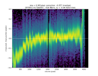
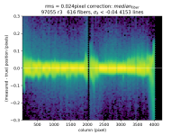
Specifically, 96938 r3 looks "good" and 97055 r3 looks "bad"
Processing the data with
reduceExposure.py /work/drp --calib /work/drp/CALIB --rerun rhl/tmp -c isr.doFlat=False isr.doFlatNir=True isr.doDark=False doAdjustDetectorMap=False doMeasureLines=False useCalexp=True --id visit=96938^97055 arm=r spectrograph=3
and then analysing it with (using drp_stella as of 2023-10-31 4:52pm EST):
from datetime import datetime
import os
import re
import numpy as np

%matplotlib ipympl
import matplotlib.pyplot as plt

import lsst.daf.persistence as dafPersist
import pfs.drp.stella.utils.stability as stability

repo = "/work/drp"

rerun = "rhl/tmp"
dataDir = os.path.join(repo, "rerun", rerun)
butler = dafPersist.Butler(dataDir)

if False:    # Quartzes going into detectorMap
    visit = 96938
else:        # quartzes taken during the run
    visit = 97055

arm, spectrograph = 'r', 3

dataId = dict(visit=visit, arm=arm, spectrograph=spectrograph)
isQuartz = True

detMap = butler.get("detectorMap_used", dataId)
als = stability.addTraceLambdaToArclines(butler.get('arcLines', dataId), detMap)

fitType = "per fiber" if False else "median" if True else None
hexBin = True   # useful with fully populated slits, or even SuNSS
nsigma = -4 # clip at nsigma, if > 0
plotWavelength = True
byRow = False       # plot dx and dy against row, not column
usePixels = True    # if True, report wavelength residuals in pixels, not nm
showChi = False
maxCentroidErr = 10
minSN = 0
lamErrMax = -0.04
soften = 0.012
arrowSize = 0.30   # for arrows and range in dx and dy plots; pixels

if True:
    fig = "tmp0"; plt.close(fig); fig = plt.figure(fig)
    fig = stability.plotArcResiduals(als, detMap, fitType=fitType, plotWavelength=plotWavelength,
                                     isQuartz=isQuartz, byRow=byRow,
                                     vmin=-arrowSize, vmax=arrowSize,
                                     title=f"{visit} {'%(arm)s%(spectrograph)d' % dataId}",
                                     usePixels=usePixels, showChi=showChi, hexBin=hexBin,
                                     soften=soften, lamErrMax=lamErrMax, nsigma=nsigma, figure=fig)
Produces the first figure  . Changing fitType from
to "per fiber" produces the second figure.
The new option should produce the second, low-residual, plot  without any extra fitting